|
To all whom it may concern:
Be it known that I, LEONARD C. WEAVER, a citizen of the United States, residing at Kirksville, in the county of Moultrie residing State of Illinois, have invented certain now and useful Improvements in Clothes-Line Supports and Tighteners, of which the following is a specification.
My invention relates to improvements in clothes-lines, more especially means for supporting and stretching the same. Its object is to provide for conveniently and effectively placing and supporting the line in position and for likewise removing the same invention necessary; and to these the invention consists of certain structural features, substantially as hereinafter fully disclosed, and particularly pointed out by the claim.
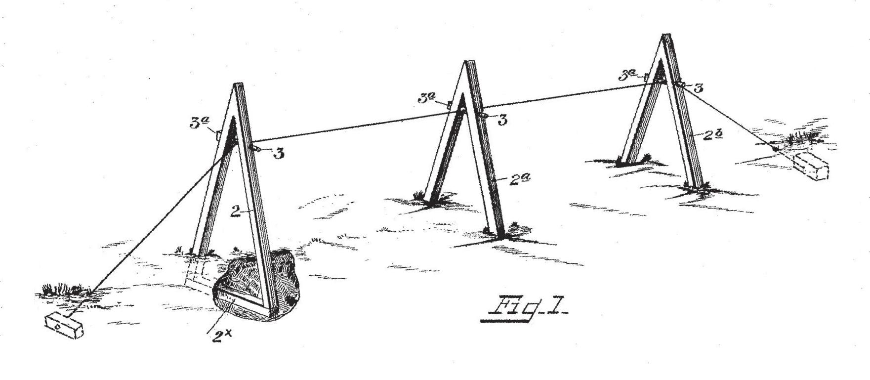
In the accompanying drawings, illustrating the preferred embodiment of my invention, Figure 1 is a view showing the application of the same for practical use. Fig. 2 is a perspective view of one of the members or contrivances embracing the features of my invention. Fig. 3 is a transverse section of the same, produced through the stretching pin or device.
In carrying out my invention I preferably anchor in the ground, as shown, or secure one end of the clothes-line or cable 1 to any suitable support or fixture, as well understood, and then or previously suitably dispose in position a number of what may be termed "props" 2 2a 2b, further described later, and after properly supporting the line thereby at suitable intervals, as also presently disclosed, similarly anchor or secure the opposite end of said line to a distant support or fixture, thus initially putting the line in position.
Each prop, preferably three being herein shown, is preferably a V-shaped casting in its initial form, and to the divergent lower ends of the legs or branches thereof is suitably secured a base or cross-piece 2", in practice suitably sunk or anchored in the ground to aid its stability. Also each casting or prop is equipped with a pin or bolt 3, having an angular head or enlargement 3a and a transverse aperture 3b therethrough, said pin being inserted through registering holes 4 41, formed in the branches or legs of the prop,
with its aperture adapted to occupy a position intermediately of said branches for the convenient reception of the line, as readily seen. The bolt-head 31 is let into a countersink or recess 5, produced in one leg or branch of the prop around the bolt-receiving opening therein for the suitable retention of the bolt or pin against turning when under stress, as presently indicated.
It is noted that as the clothes-line is passed through the aperture of the bolt of the first prop 2 said bolt is suitably manipulated or adjusted to requisitely stress the line for the initial retention of said prop in place and that after said line has been similarly passed through the respective apertured bolts of the other props 2a 2b and their bolts in like manner adjusted or manipulated and the distant end of the line made fast the line is finally stressed or stretched by suitably manipulating the pin or bolt of the intermediate prop 2a, thus drawing upon the line or cable from both directions in the line of its axis, thereby more effectively stressing or stretching the line than would otherwise be the case, as is apparent. This is readily effected by applying a wrench to the head of the bolt of said prop and suitably turning the same for accordingly being said bolt, the wrench of course being removed when the requisite tension has been imparted to the line and the bolt forcibly moved until its head has been suitable let into the opposed recess in the prop, the bolts of the other props being adjusted in keeping with the aforesaid manipulation of the bolt of the intermediate prop.
I claim
A device of the character described comprising end and intermediate props each having diagonal uprights with their lower divergent ends connected together by a base member to brace and aid the retention of the same in planted position in the ground, and each having an angular-headed pin provided with a longitudinal slot opening laterally therethrough, said pin being arranged in registering apertures in the convergent portions of said uprights near the extreme upper ends thereof, each of said props having one of its uprights provided, around the pin-receiving aperture therein, with a recess forming an enlargement of one end of said aperture, and a line passing through the slots of said pins and having its ends adapted to be anchored in place to permit its stressing in said slots as said pins are suitably actuated, said pins having their angular heads adapted to be let into said recesses.
In testimony whereof I have signed my name to this specification in the presence of two subscribing, witnesses.
LEONARD C. WEAVER.
Witnesses:
M. DOUTHIT,
BRAZ D. TULL.
|