To all whom it may concern:
Be it known that we, WILLIAM H. MONROE and EDDY G. MONROE, citizens of the United States, residing
at Sullivan, in the county of Moultrie and State of Illinois, have invented certain new and useful
Improvements in Motors for Churns; and we do declare the following to be a full, clear, and exact
description of the invention, such as will enable others skilled in the art to which it appertains
to make and use the same, reference being had to the accompanying drawings, and to the letters of
reference marked thereon, which form a part of this specification.
Our invention relates to improvements in motors for churns and it consists in certain novel features
hereinafter described and claimed.
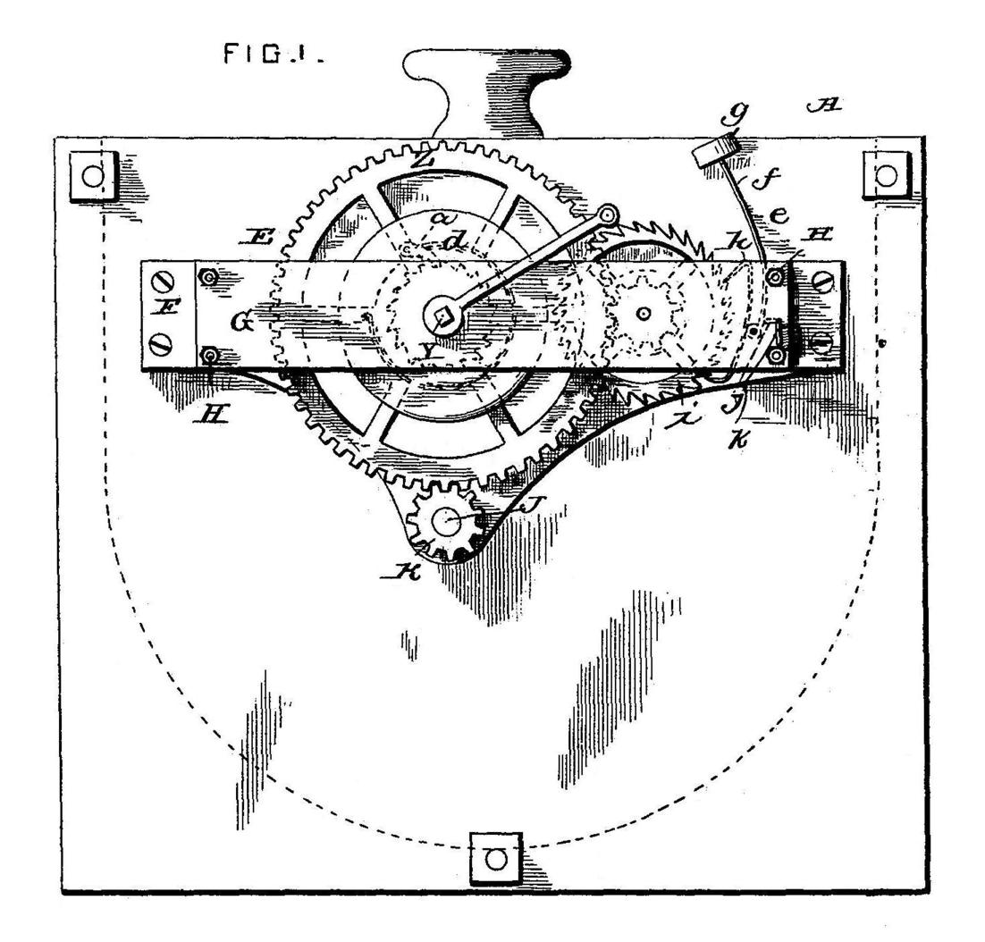
In the annexed drawings, which fully illustrate our invention, Figure 1 is a side elevation of a
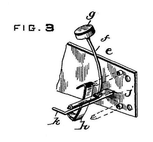
churn provided with our improvements. Fig. 2 is a transverse vertical section of the same; and Fig. 3
is a detail view of the governor and brake for the operating mechanism.
The churn body A may be of any desired size or material. On one side of the churn body, near the
top of the same, we secure the frame E which consists of two plates F G which are secured together
and to the churn body by suitable bolts and are held at the proper distance apart by the distance
rods H, as shown. These plates provide bearings for the several shafts of the operating mechanism
and consequently obviate the necessity of forming such bearings in the side of the churn body which
construction would wear away the body and permit the same to leak. The inner plate F is provided with
a depending extension I in the lower extremity of which we journal a short shaft J having a pinion K
on its outer end and provided with an annular socket L in its inner end. The socket L is engaged by
the angular stub shaft M at one end of the dasher and the motion of the shaft J is thereby transmitted
directly to the dasher so as to rotate the same. The opposite end of the dasher is provided with a
cylindrical pintle or trunnion N which engages a bearing plate 0 secured on the inner face of the side
of the churn body, as shown.
The driving shaft Y is mounted in the plates F G and has mounted loosely upon it, a gear wheel Z which
meshes with the pinion K, as clearly shown. This gear wheel carries a pawl a which engages a ratchet
wheel or disk b secured rigidly on the driving shaft so that when the said shaft is moved in one
direction, no motion will be imparted to the driving wheel but when the shaft rotates in the opposite
direction, the said wheel will be carried around therewith and the churn operated. The driving shaft
is rotated by means of a spring c which has one end secured to the said shaft and the other end secured
to the inclosing drum d. When it is desired to operate the churn, a crank handle is fitted on the outer
end of the driving shaft and the shaft thereby rotated so as to wind up and tighten the said spring.
When the crank handle is released, of course, the spring unwinds and rotates the driving shaft.
In order that the motor may be operated with a steady and regular movement, we provide the governor >e
which consists of a vibratory arm f pivoted on the side of the churn body and having a weight g at
its upper end and provided with an escapement pawl h at its lower end which engages an escapement wheel i
mounted within the frame e and driven from the driving shaft, as shown and as will be readily understood.
In order that the mechanism may be stopped at any desired moment and a loss of energy exerted by the
driving spring be thereby prevented, we arrange a cam j adjacent to the lower end of the escapement
lever and provide the said cam with a crank handle k projecting beyond the outer face of the frame E,
as shown. By turning this cam inward so as bind against the escapement lever the said lever will be
forced against the escapement wheel so strongly as to prevent the rotation of the same and consequently
stop the operation of the device.
It is thought the operation and advantages of our device will be readily understood from the foregoing
description. The cream is placed in the churn body and the driving spring wound, after which, the brake
being removed, the dasher will be automatically rotated and the churning operation performed. When the
churning operation is finished, the brake cam is turned so as to stop the machine as above described,
when the dasher and the butter can be easily removed.
By providing means for stopping the operation of the device at will we overcome the necessity of allowing
the spring to run down and consequently we increase the efficiency and prolong the life of the spring.
Having thus described our invention, what we claim, and desire to secure by Letters Patent, is --
The combination with the plates F G secured upon the side of the churn body, and the operating gearing
mounted between said plates and having an escapement wheel i, of a vibratory arm pivoted near its lower
end on the side of the churn body, an escapement pawl at the lower end of said arm engaging the escapement
wheel, a weight secured to the upper end of the vibratory arm, and a cam mounted on the side of the churn
body within the path of vibration of the vibratory arm and adapted to bind against the side of said arm,
and provided with a handle extending beyond the plate G.
In testimony whereof we affix our signatures in presence of two witnesses.
WILLIAM H. MONROE.
EDDY G. MONROE.
Witnesses:
F. M. HARBOUGH,
WILLIAM H. WHITAKER.