|
To all whom it may concern:
Be it known that we, WILLIAM A. McMULLIN and FRANK E. RITTENHOUSE, Citizens of the United States, residing at Lovington, in the county of Moultrie, State of Illinois, have invented a new and useful Invalid-Bed, of which the following is a specification.
The present invention appertains to invalid beds, and is particularly an improvement over the invalid bed disclosed in the co-pending application Serial No. 865,046 filed October 28, 1914.
It is the object of the present invention to provide an invalid bed having novel and improved features of construction to enhance the utility and efficiency thereof.
The improved invalid bed embodies novel means for raising and lowering the mattress below the webbing which supports the invalid, novel means for attaching the webbing to the frame, novel means for adjusting the head rest, and a novel bracket for supporting a book, tray or other object in a convenient position adjacent the patient.
With the foregoing and other objects in view which will appear as the description proceeds, the invention resides in the combination and arrangement of parts and in the details of construction hereinafter described and claimed, it being understood that changes in the precise embodiment of the invention herein disclosed can be made within the scope of what is claimed without departing from the spirit of the invention.
The invention is illustrated in the accompanying drawings, wherein:
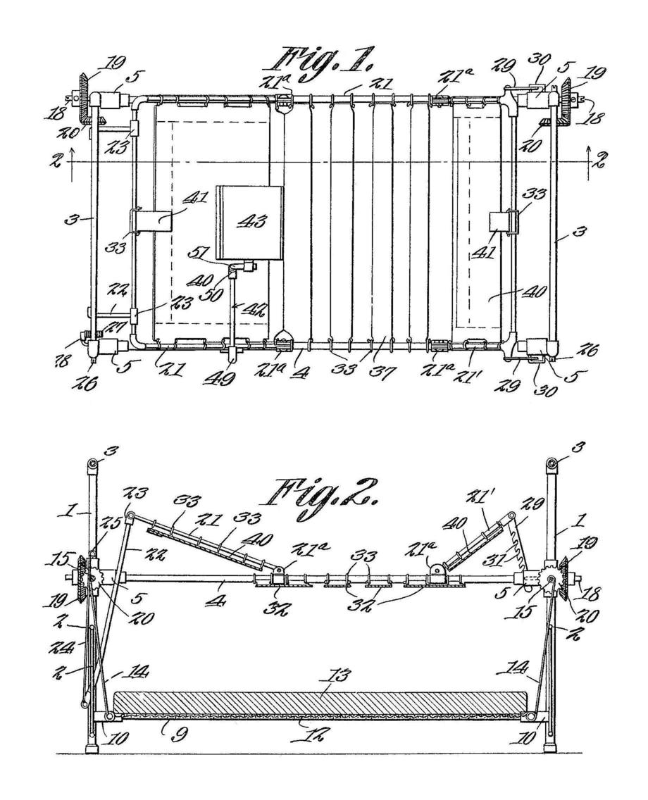
Figure 1 is a plan view of the improved bed.
Fig. 2 is a longitudinal section thereof taken on the line 2-2 of Fig. 1.
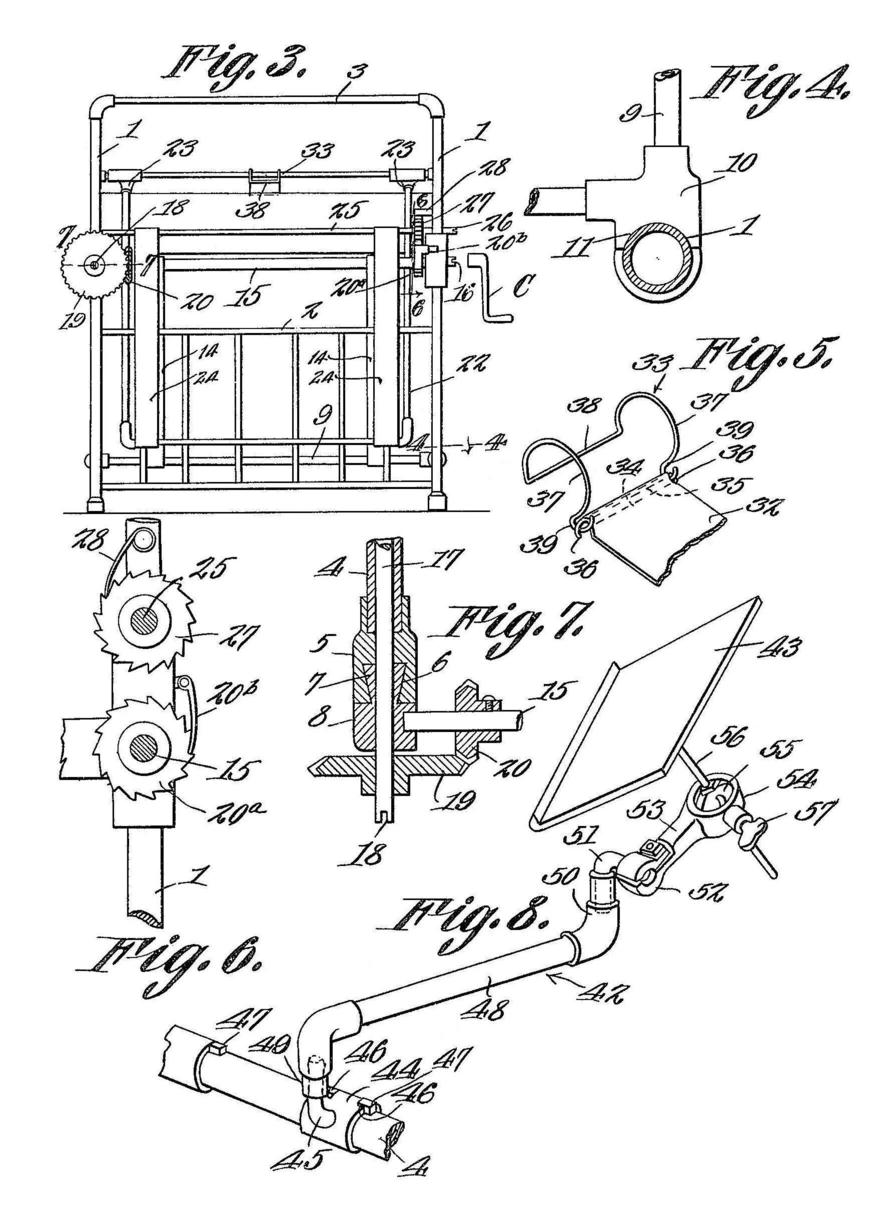
Fig. 3 illustrates the head end of the bed. Fig. 4 is an enlarged. sectional detail taken on the line 4-4 of Fig. 3.
Fig. 5 is an enlarged perspective view of one of the clips for attaching the webbing to the frame.
Figs. 6 and 7 are enlarged sectional details taken on the lines 6-6 and 7-7, respectively, of Fig. 3.
Fig. 8 is an enlarged perspective view of the bracket.
The frame of the bed comprises two ends, each embodying a pair of corner posts or legs 1 connected adjacent their lower ends by cross members 2, and adjacent their upper ends by cross members 3. The frame includes a pair of longitudinal side rails 4 which are tubular, and which have their ends engaged within castings or blocks 5 that are provided with dove-tailed recesses 6 fitting over the dove-tailed projections 7 of castings or members 8 forming a part of the posts 1. The castings 8 are disposed between the ends of the posts, and the castings 5 being fitted downwardly over the projections 7 so as to rigidly secure the rails and ends together, to render the frame substantial in construction.
Mounted for vertical movement within the frame below the rails 4 thereof is a rectangular horizontal mattress frame 9 having the corner castings 10 connecting the longitudinal and cross members thereof, and the castings 10 are provided with curved recesses 10 slidably engaging the tubular posts 1, to guide the frame 9 for vertical movement, and to prevent the horizontal displacement thereof. The frame 9 has a suitable spring 12 secured therein, which supports a mattress 13.
The means for adjusting the frame 9 vertically embodies tapes or flexible elements 14 attached to the ends of the frame 9 and extending upwardly and having their upper ends attached to cross or transverse end shafts 15 journaled to the castings S. The shafts 15 are journaled through the castings 8 at one side of the bed and the respective ends are formed, as at 16, for the engagement of a suitable crank C, while the other ends of the shafts 15 are journaled within but do not extend through the castings 8 at the other side of the bed as illustrated in Fig. 7. A longitudinal shaft 17 disposed at the last mentioned side of the bed extends through the respective rail 4 and is journaled through the respective castings 5 and 8, as indicated in Fig. 7, and the protruding ends of the shaft 17 are formed, as at 18, for the engagement of the crank C. The shafts 15 and 17 are operatively connected, and to this end, bevel gears 1.9 are secured to the protruding ends of the shaft 17 and intermesh with bevel gears 20 secured to the shafts 15. Consequently, when one of the shafts is rotated, the others will also rotate in unison therewith, it being noted that the shafts 15 and 17 are provided with the crank engaging portions 10 and 18 at the four corners of the bed, so that the crank C may be applied at any corner of the bed for conveniently rotating the shafts. When the shafts 15 are rotated, the tapes 14 can be wound thereon for raising the frame 9, or the tapes 14 may be allowed to unwind for lowering the said frame 9.
In order to normally prevent the unwinding of the tapes 14 from the shafts or rollers 15, a ratchet wheel 20a is secured to the shaft 15 at the head end of the bed adjacent that side of the bed opposite the shaft 17 and a pawl or ratchet 20b pivoted to the respective casting 8 normally engages the ratchet wheel 20a to prevent the rotation of the said shaft 15, and consequently all of the shaft. When the pawl 20b is disengaged from the ratchet wheel, the tapes 14 are allowed to unwind from the shaft 15, so as to permit the frame 9 to gravitate.
The head rest embodies a U-shaped member or frame 21 having its ends pivoted to clips 21a embracing the rails 4 between the ends thereof. The bed is also provided -with a foot rest embodying a U-shaped member or frame 21' having its ends pivoted to clips 21a embracing the rails 4. The head and foot rests can normally be swung downwardly onto the rails 4, and can be raised or swung upwardly when desired or necessary.
The means for adjusting the head rest embodies a U-shaped prop 22 having the terminal bearings or sleeves 23 loosely embracing the intermediate or yoke portion of the member 21. The prop 22 projects downwardly from the headrest and its limbs pass through the cross member 2 of the head end of the bed. Tapes or flexible elements 24 have their lower ends attached to the intermediate or yoke portion of' the prop 22, which is located at the lower or free end of the prop, and the upper ends of the tapes are attached to a transverse shaft 25 located above the shaft 15 at the head end of the bed. The ends of the shaft 25 are journaled through the posts 1 of the- head end of the bed, and one end of the shaft 25 which protrudes from the respective leg or post is formed, as at 26, for the engagement of the crank C, whereby the shaft 25 can be rotated conveniently. When the shaft 25 is rotated to wind the tapes 24 thereon, the prop 22 is raised, and this wills-wing the head rest upwardly, and when the shaft 25 is released, the tapes 24 can unwind therefrom to allow the head rest to move to normal horizontal position. A ratchet wheel 27 is secured upon the shaft 25 above the ratchet wheel 20a and a pawl or clog 28 is pivoted to the respective post 1 and normally engages the ratchet wheel 27 for preventing the shaft 25 from rotating so as to allow the tapes 24 to unwind therefrom. Thus, when the tapes 24 are wound upon the shaft 25, the pawl 28 in engaging the ratchet wheel 27 prevents the tapes from unwinding, and by disengaging the pawl 28, the tapes 24 are allowed to unwind for lowering the head rest.
The means for adjustably supporting the foot rest embodies bars 29 having their P- per ends pivoted to the member 21' and passing slidably through staples or. loops 30 attached to the castings 5 at the foot end of the bed, the bars 29 having notches 31 engageable with the, staples 30, whereby the foot rest may be, supported at various angles, the wine as the head rest. When the foot rest is raised to the desired position, the bars 29 can be engaged to the staples for supporting the foot rest, and whore the bars 29 are disengaged from the staples 30, the bars 29 may move downwardly when the foot rest is lowered.
Supported between the rails 4 of the bed frame area plurality of transverse webbings or strips of canvas, duck or other suitable flexible material, and the ends of the webbings 32 are attached by means of clips 33 to the rails 4. The webbings 32 are provided at their ends with hems 34 through which rods 35 extend, the ends of the rods 35 having hooks or angularly extending portions 36. The clips n are each formed from a length 'of resilient wire, and. having a pair of spaced arcuate portions 37 extending through an angle of more than 180° so that the portions 37 can be snapped over the rails 4 to embrace the same.
The portions 37 are connected at one end by a yoke 38, and have the hooks 39 at their other ends with which the hooks or angular portions 36 of the rods 35 are engageable.
The clips 33 are snapped upon and embrace the rails 4, and the ends of the webbings 32 are detachably engaged to the clips, the, rods 35 being engaged to the hooks 39 of the clips. The webbings may not only be detached from the clips, but the clips can also be detached from and adjusted upon the rails 4.
The head and foot rest are also each equipped with transverse webbing 40 of the same material as the webbing 32, and the ends of the webbings 40 are attached to the limbs of the members 21 and 21' with clips 33, the same as those by which the webbings 32 are attached to the rails. Each of the webbings 40 has a flap 41 which is attached by a clip 33 to the intermediate portion or yoke of the respective member 21 or 21'.
A bracket 42 is carried by one rail 4 of the bed frame for supporting the board or table 43. This bracket 42 embodies a sleeve 44 mounted for sliding and rotary movement upon the respective rail 4, and having at its outer side an. upstanding finger or pintle 45. The sleeve 44 is provided at its ends with notches 46 engageable with upstanding lugs 47 with which the respective rail 4 is provided. The lugs 47 are spaced apart so that the sleeve 44 can be slid longitudinally to two different positions, the notches 46 being adapted to receive the lugs 47 whereby the sleeve is held against rotary movement. When the sleeve 44 is slid to an intermediate position between the lugs 47, the sleeve 44 can rotate to allow the bracket to be swung downwardly out of the way. The bracket also includes an approximately horizontal arm 48 having a down turned socket portion 49 at one end fitting rotatably upon the finger 45, and the other or free end of the arm 48 is provided with an upstanding socket portion 50 rotatably receiving the downwardly projecting arm of an L-shaped member 51. The other arm of the member 51 which projects horizontally is embraced by the clamp 52 of the member 53, and the other or free end of the member 53 has an annular portion 54 in which a ball 55 is disposed for turning movements in various directions. A shank or stem 56 is secured through the ball 55, and is attached at its upper end to the board 43, and a set screw 57 is carried by the portion 54 for engaging the ball 55 and holding it at any position to which it is turned.
The arm 48 can be swung horizontally to move the board 43 forwardly, rearwardly and sidewise, and the member 51 can be rotated about a vertical axis to assist in the proper positioning of the board 43. The member 53 can be swung about a horizontal axis when the clamp 52 is loosened, and when the set, screw 57 is loosened, the shank or stem 56 can be swung at various angles with respect to the member 53. This allows the board 43 to be properly positioned for either holding a book, a tray or other object, according to the use of the bracket. When the bracket is not in use, it can be swung out of the way by sliding the sleeve 44 away from the respective lug 47, which allows the bracket to be swung downwardly. It is also to be noted that the sleeve 44 can be slid into engagement with either of the lugs 47 for holding the bracket at two different longitudinal positions of the bed.
Ordinarily, the frame 9 is raised to bring the mattress 15 against the webbings 32 and 40, whereby the patient is supported by the mattress and. spring in a comfortable manner. When it is necessary for the patient or invalid to respond to the calls of nature, the frame 9 is lowered, and the invalid is then supported by the webbings 32 and 40. A bed pan or vessel may then be seated upon the mattress 13, the webbings 32 having been slid or adjusted longitudinally to provide an opening above the pan or vessel. After the vessel is removed, the frame 9 can be raised. The foot and head rests can also be raised and lowered to suit the comfort of the invalid or patient. The webbings 32 can be adjusted according to the requirements, and can also be detached and washed. The webbings 40 are each attached at each end by a number of clips 33 to the head or foot rest member, whichever is the case, and the ends of the webbings 40 are naturally provided with a corresponding number of hems 34 and rods 35. The webbings 32 below the pivoted portions of the head and foot rests are relatively wide so as to project in front and rear of the pivoted portions of the head and foot rests, and each of the end webbings 32 has each end connected by a pair of clips 33 to the respective rail 4 at the opposite sides of the respective clip 21a.
Having thus described the invention, what is claimed as new is:
- An invalid bed comprising a bed frame including corner posts and longitudinal rails, connecting blocks attached to the ends of the rails, said blocks and posts having interfitting dove-tailed portions, webbing supported by the rails, a mattress frame movable vertically below the webbing, transverse shafts rotatably carried by the posts, flexible elements attached to the mattress frame and said shafts to be wound thereon, one of said rails being tubular, and a longitudinal shaft extending through said tubular rail and respective blocks and posts and having its ends operatively connected with the aforesaid shafts.
- An invalid bed comprising a bed frame including corner posts and longitudinal rails connecting them, webbing supported by the rails, a vertically movable mattress frame below the webbing, transverse shafts journaled to the posts, flexible elements attached to the mattress frame and to said shafts, one of the rails being tubular, a longitudinal shaft extending through the tubular rail and having its end portions extending through and projecting from the respective posts, bevel gears secured upon the protruding portions of the longitudinal shaft, and bevel gears intermeshing with said bevel gears and secured upon the transverse shafts.
- In an invalid bed, a bed frame, detachable clips embodying arcuate portions snapped over and embracing portions of the frame, the clips having hooks, a webbing, and rods attached to the ends of the webbing and engaging said hooks.
- In an invalid bed, a bed frame, clips embracing portions of the frame, each clip being formed from a length of wire and embodying arcuate portions having hooks, and a yoke connecting said arcuate portions, the arcuate portions extending through an arc of more than 180°, a webbing having end hems, and rods extending through said hems and having angularly extending end portions engaging said hooks.
In testimony that we claim the foregoing as our own, we have hereto affixed our signatures in the presence of two witnesses.
WILLIAM A. McMULLIN.
FRANK E. RITTENHOUSE.
Witnesses:
ED HARMON,
A.R. AULT.
|