To all whom it may concern:
Be it known that we, CHARLES 0. McKINNEY and LUTHER PERRY, citizens of the United States, residing at Bethany, in the county of Moultrie, State of Illinois, have invented a new and useful Rivet Anvil and Remover, of which the following is a specification.
This invention relates to the general. Class of metal forging and welding, and more especially to riveting machines which are supported by the work; and the object of the same is to produce a unitary portable tool which is at once an anvil to assist in the insertion of a rivet and a punch for removing an old or useless rivet.
More especially this tool is adapted for use in inserting rivets in and removing them from the tops of buggies or carriages, and to those familiar with this work it will be clear that conditions often arise rendering it extremely difficult for the workman to gain access to points where the rivet is to be handled, more particularly because the carriage top is usually fastened to the bows and it is undesirable to remove it therefrom.
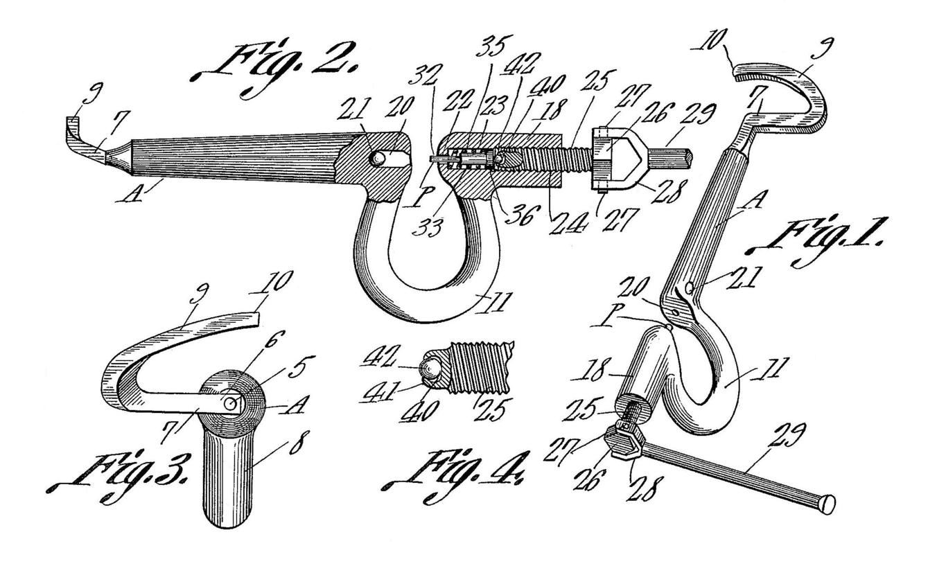
The following specification describes the preferred manner of carrying out our invention, reference being had to the accompanying drawings wherein Figure 1 is a general perspective view of this tool complete and ready for use. Fig. 2 is a side elevation thereof with parts in section. Fig. 3 is an end elevation of the anvil extremity of the tool. Fig. 4 is a detail which will be referred to hereinafter.
In the drawings, the letter A designates broadly the anvil end of this tool and the letter P designates broadly the punch thereof. While these two elements are separate in fact and opposite in function, they are here assembled upon one body not only for purposes of convenience but because the presence of the punch on the anvil body gives the body weight which tends to hold it in position as will be explained below.
The rivet inserter or anvil A is, specifically, but a depression or cavity made in the face 6 of the anvil proper 7 which is here shown as a bar of substantially rectangular cross section projecting at right angles from one extremity of the body 8 of this tool. The outer end of this bar 7 is bent into a hook 9 which curves around beyond the base 6 of the anvil as seen in Fig. 1 and stands at an angle thereto as seen in Fig. 3, its extremity or tip projecting beyond a vertical line drawn through the cavity 5. From the anvil the body of the tool projects straight to the rear as seen in Fig. 2, is continued into a loop 11 of substantially horse-shoe shape, and yet beyond the loop is projected into a rear end 18, this construction being not only adapted to the punch P but also affording considerable weight to the body for a purpose which will be clear. When it is desired to use this device as an anvil to assist in the insertion of a rivet through the carriage top, the hook 9 is passed around behind one or more of the carriage top bows and the curtain or curtains at the point where the rivet is to be inserted is or are drawn across the bar 7 so that the extremity of the rivet lies in the cavity 5. In this position, the heavy rear end of the body may be released and by its weight it cants the whole so that the hook draws inward toward the bow and the anvil base 6 is pressed outward toward the bow and the cavity is brought directly against g the extremity of the rivet so that the latter can be pounded upon with a riveting hammer in a manner which will be well understood to those familiar with this art. As soon as the rivet has been upset, by lifting the rear end 18 of the body the whole tool can be instantly removed from place for repeated use at another point. Thus it will be seen that the pressure of this tool does away for the need of a second workman to hold the anvil while the first workman upsets the rivet, because the heavy body combined with the peculiar disposition of the hook causes the anvil to hold itself in place upon the carriage bow.
The rivet remover or punch P works across the space between the adjacent extremities of the loop 11 as shown best in Fig. 2. In the face of one extremity is a socket 20 from whose rear end leads a side exit 21. Through the face of the other end of the loop is formed a hole 22 communicating with an interior longitudinal and enlarged cavity 23 within the rear arm 18 of the body, and the rear extremity of this cavity is internally threaded as shown at 24. These threads are engaged by other threads on a screw 25 having a head 26 at its outer end, and on diametrically disposed pins 27 in said head is pivoted a yoke 28 at the inner end of a lever or handle 29. By throwing this lever to one side as seen in Fig. 1 and then revolving it bodily around the screw, the latter can be turned in either direction so as to project it into or withdraw it from the rear end 18 of the body of the punch. What might be called the punch proper is a member removably inserted into the cavity 23 and comprising a body 33 of smaller diameter than the said cavity, a reduced tip 32 projecting from said body through the hole 22, and an enlarged head 36 at the extremity opposite from said tip; and around said body within the cavity is disposed a coiled spring 35 bearing the head 36 normally away from the end of the cavity and hence normally withdrawing the punch from working position. The inner end of the screw 25 is provided with a socket 40 best seen in Fig. 4, and the lips of this socket are bent inward so as to loosely engage a ball 42 like the ordinary caster, and this steel ball rests upon the head 36 and forms an anti-friction device between the screw and punch. Hence when the former is rotated by the lever 29 the latter is either borne forward if the screw be turned to the right or borne to the rear by the spring if the screw be turned to the left, but in either case the punch is not necessarily rotated within the socket, although it is also not necessarily prevented positively from rotating. In the act of using this punch or remover for the purpose of withdrawing from the carriage curtain a rivet which is no longer useful, the upset end thereof is by preference first cut off, although this is in fact not absolutely necessary, and then the curtain with the rivet in it is brought into position between the extremities of the loop 11 and exactly over the socket 20. The lever 29 then being turned in the proper direction to advance the screw 25, the punch is projected (to the left in Fig. 2) and its tip 32 moves forward against the shank of the rivet and slowly but firmly pushes the latter out of place, the unused part falling into the socket 20 and out the exit 21. The lever is then rapidly rotated in the reverse direction to withdraw the screw 25, and the expansion of the spring 35 causes the punch to retract which would be to the right in Fig. 2.
While it is true that the anvil is idle while the punch is being used, the hook 9 is of fully as much service to the punch as it is to the anvil because it may be passed astride some upright member, such for instance as one of the carriage bows, to support the tool body 8 in a horizontal position and at exactly the proper point desired. Hence it might be said that the hook answers as a support for either the anvil or the punch, and in either case the weight of the body cooperates with the position of the hook to cause the latter to hold itself automatically in place.
All parts are by preference of metal and of the desired shape and configuration in detail which the manufacturer or user may desire.
What is claimed is:
In an implement of the character described, the combination with a horizontal body having a depending loop between its ends, an arm projecting at right angles to the length of said body from one end thereof and standing horizontal when said loop stands vertical, and a hook continuing from the outer end of said arm in a plane removed from its outer face and in a direction obliquely upward when said aim stands horizontal; of a plurality of tools mounted on said body.
In an implement of the character described, the combination with a horizontal body having a depending loop between its ends, an arm projecting at an angle to the length of said body from one end thereof and standing horizontal when said loop stands vertical, and a hook continuing from the outer end of said arm in a plane removed from its outer face and in a direction obliquely upward when said arm stands horizontal; of a riveting anvil consisting of a cavity formed in the outer face of said arm.
In an implement of the character described, the combination with a heavy body having a depending loop between its ends, an arm projecting at an angle to the length of said body from one end thereof and standing substantially horizontal when said loop stands vertical, and a hook continuing from the outer end of said arm in a plane removed from its outer face and in a line above its body when said arm stands horizontal; of a rivet remover comprising a socket in one face of said loop, a punch movably mounted in the rear end of the body and in axial alinement with said socket, and means for projecting and retracting the punch.
In a rivet remover, the combination with a body having a horseshoe-shaped loop between its ends, one of the latter having a socket with a side exit and the other having a longitudinal cavity threaded at its rear end and provided with a reduced hole at its front end standing along the projected axis of said socket; of a punch proper including a body within said cavity having an enlarged head at its rear end and a reduced tip at its front end projecting through said hole, an expansive spring coiled around said body between the head and the end of the cavity, a screw taking into said threads and having operating means at its outer end and a socket in its inner end with inturned lips surrounding said socket, and an anti-friction ball held by said lips and bearing against the head of the punch.
In testimony that we claim the foregoing as our own, we have hereto affixed our signatures in the presence of two witnesses.
CHARLES O. McKINNEY.
LUTHER PERRY.
Witnesses:
H. A. MULHOLLAND, C. E. Heckler.