To all whom it May concern:
Be it known that we, MICHAEL MCCARTHY and JOHN H. WEHMHOFF, of Dalton City, in the county of Moultrie
and State of Illinois, have invented a new and useful Improvement in Portable Elevators, of which the
following is a specification.
Our invention is an improvement in that class of portable elevators that are provided with transporting-wheels
and a platform, onto which loaded wagons may be driven and then hoisted at one end for dumping their load
into a box that slides vertically and is adapted to be tilted to discharge its contents.
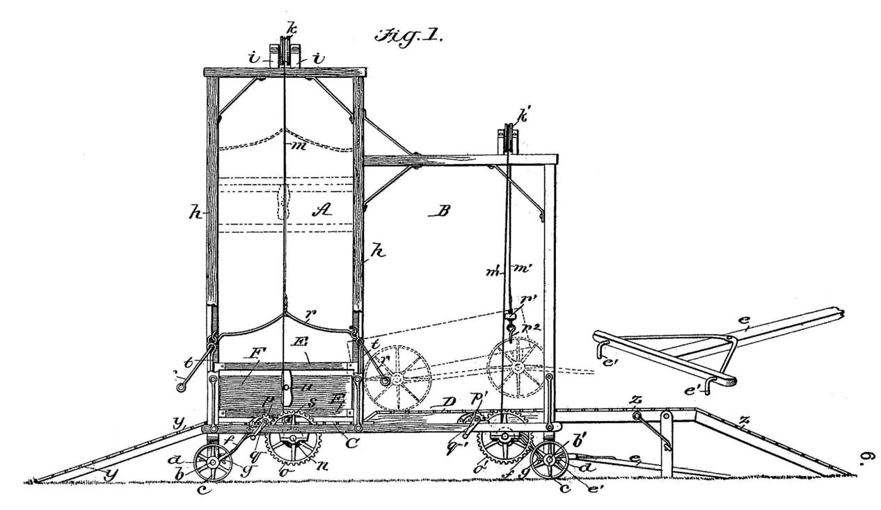
In accompanying drawings, three sheets, Figure 1 is a side view of our apparatus. Fig. 2 is a horizontal
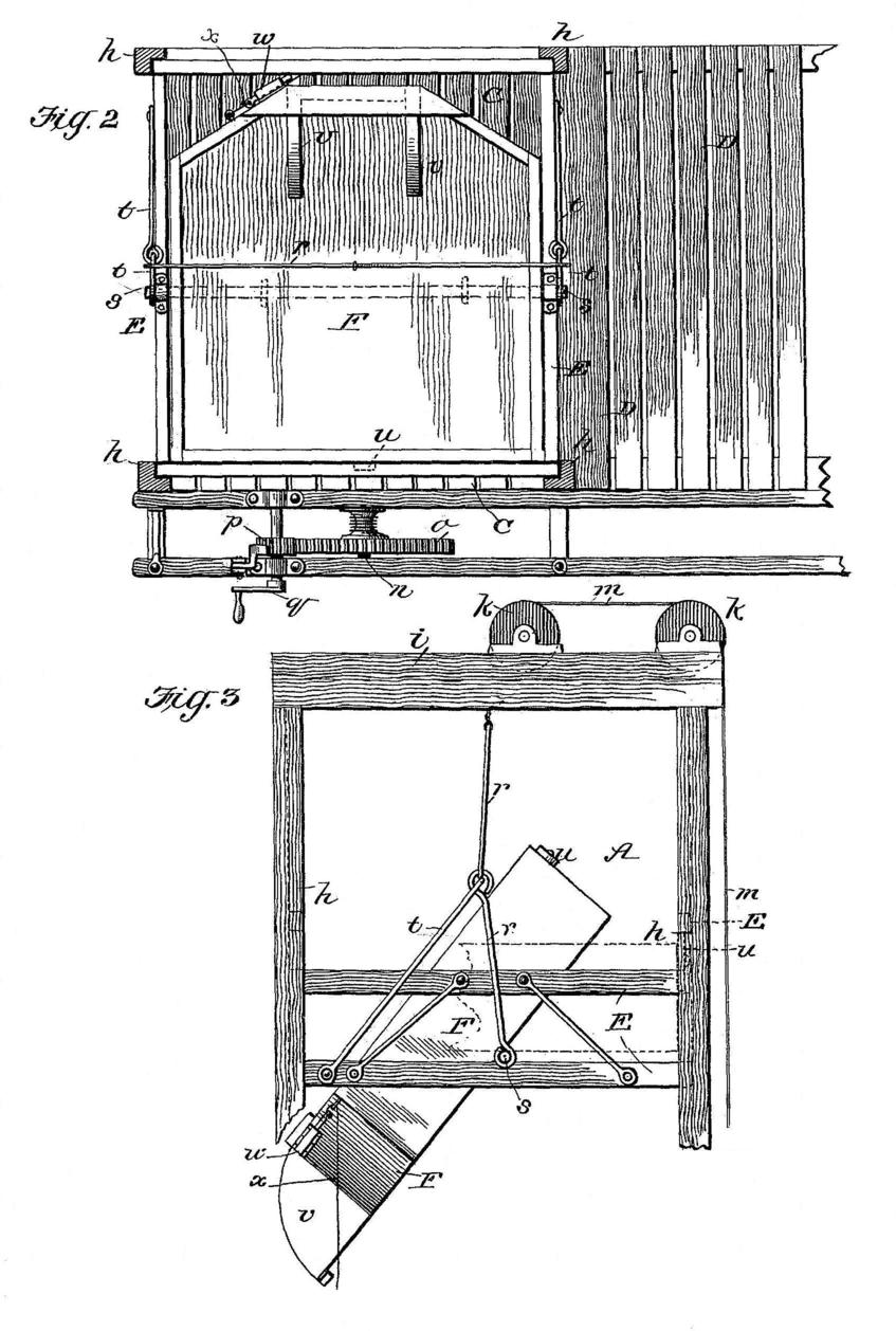
section, enlarged, of the main portion of the apparatus. Fig. 3 is a side view, enlarged, of the top
portion of the apparatus. Fig. 4 is a vertical section of the apparatus. Fig. 5 is a horizontal detail
section. Fig. 6 is a perspective view, enlarged, of a portion of the hopper, showing the hinged discharge-spout
open. Fig. 7 is a perspective view of the same parts, showing the spout closed.
The elevator-frame consists of two connected upright portions A and B, which are of unequal height, and
a horizontal rectangular base composed of two parts C and D, which are arranged at different heights. The
base C D is supported at its ends on pivoted axles b b', having truck-wheels c. Each axle is provided with
staples or clips d for attachment of a pole or tongue e for use in guiding the elevator while moving it
from place to place. The tongue e is provided with hooks e', and thus adapted to be easily detached from
one axle b and attached to the other b', as required for hauling the elevator with either end forward. One
or both axles must be locked in position when the elevator is being hauled, and for this purpose we employ
stay-rods f, Fig. 4, which are pivoted to the base-frame and whose free ends engage staples or eyes g,
attached to the axles near their ends. The part A of the upright framework is formed of parallel posts h
and top crossbars i, on which two pulleys k are mounted. A rope m runs on said pulleys and extends down
to a shaft n, hung in bearings on the side of the base, and having a cog-gear o, that meshes with a pinion p
on a crank-shaft q. A pivoted locking-pawl engages said gear, as shown.
The rope m connects with the hinged bail
r of a skeleton cage E, that slides on and between - the four posts of the frame part A. Within said
cage E is arranged a tilting box F, the same being supported and eccentrically hinged on a shaft s, that
extends transversely. of the lower portion of the cage E, and is fixed thereto, Figs 2 and 3. The afore-
said bail r is detachably connected with the ends of this shaft s and is held normally in vertical position
by means of diagonal braces t, Fig. 3, pivoted. to opposite sides of the cage and engaging the bail at
its joints, as shown. It is apparent that if the lower ends of the jointed bail-pieces be detached from
the shaft s it may be swung back out of the way, for a purpose hereinafter stated.
The box F is held in normal horizontal position in the cage E by means of a catch or locking device. The
latter consists of a bar or button u, pivoted to the rear side of the box F and adapted to engage the
horizontal bars forming the adjacent portion of the cage E. When adjusted in vertical position, the device u
holds or locks the box F in horizontal position, and when turned it allows the box to tilt or dump by gravity
and thus discharge its contents. The box F is provided with a hinged discharge-spout v, which, when in raised
position, forms also a portion of its side - that is to say, spout v is hinged to the bottom of the box F, and
when raised fits in the opening in the side of the same and closes it.
A locking device w, operated by a pull-cord x, holds the spout in its closed position. The sides of the box
adjacent to the spout are inclined outward to facilitate discharge of the load, as will be readily understood.
A slatted removable incline y is provided at one end of the base C D and a hinged and foldable incline , z
at the other end. The hinged portion of the latter, z, is supported when in use by blocks or other form of
stay. On the side of the base of the elevator, opposite the raised platform D, are arranged a cog-gear o',
pinion 21, and crank-shaft q', similar to those before described, for use in elevating and lowering the box F.
A rope m' runs on pulleys 7c', mounted on cross-bars of the upright frame part B. The said rope m' suspends
a bar r', having hooks r2, as shown.
The elevator is used as follows: The cage E and box F being elevated, as shown by dotted lines in Fig. 1, a
loaded wagon is driven up the incline y, beneath the cage E, and drawn onto the higher portion D of the platform,
the team proper being advanced so as to stand on the hinged incline z. The cage E is then lowered, and the bail
detached from its shaft s and swung back out of the way, as shown. (See Fig. 5.) The hooks r2 of the grapple and
hoisting apparatus are then attached to the fellies of the front wheels of the wagon, and, the gearing o' p' q'
being rotated, the front end of the wagon is elevated, thus causing its contents to discharge into the box F.
The cage E is then elevated and the spout unlocked, and the box released to allow it to tilt and dump its load
into a granary or other receptacle.
It is apparent that the elevator may be easily hauled from place to place and used for elevating grain or other
commodity, whether received from a wagon or otherwise.
Having thus described our invention, what we claim as new, and desire to secure by Letters Patent, is --
1. The portable elevator having a wheeled axle pivoted at each end thereof and provided with staples, or eyes,
on their inner sides, and
hooks pivoted on the sides of the base-frame, and adapted to engage said staples, as shown and described.
2. In a portable elevator, the combination, with the vertical guide-frame h, and a cage, E, which is slidable
therein, of the box F, an axle supporting said box, which is eccentrically mounted thereon, and a button pivoted
to the back of the box and arranged as shown and described, whereby it is adapted to engage the frame of the cage,
when adjusted vertically, and thus holds the box in horizontal position, as specified.
3. In a portable elevator, the combination, with the vertical guide-frame, a cage which is slidable therein,
an axle arranged in the cage, a box mounted eccentrically on the axle, a bail adapted for detachable connection
with the ends of the axle, and braces pivoted to the cage, and their free ends being jointed to the vertical
side portions of the bail, and means connected with the latter for hoisting the cage, as shown and described.
4. In an elevator, the combination, with vertical guides, of a slidable cage, a box hinged therein, a bail
which is detachable from the cage, and pivoted diagonal braces for supporting said bail in normal position,
as shown and described.
MICHAEL McCARTHY.
JOHN II. WEHMHOFF.
Witnesses:
CORNELIUS MCCARTHY,
JACOB DARSEEN.