To all whom it may concern:
Be it known that I, MARTIN V. B. KENNEY, a citizen of the United States, residing at
Cushman, in the county of Moultrie and State of Illinois, have invented certain new and useful
Improvements in Hay-Derricks, of which the following is a specification.
The object of my invention is to produce a hay-derrick that can be cheaply constructed
and economically operated, and which can be used for a variety of purposes besides stacking hay.
My invention consists in certain peculiarities of construction and combinations of parts,
as will be hereinafter specified and claimed.
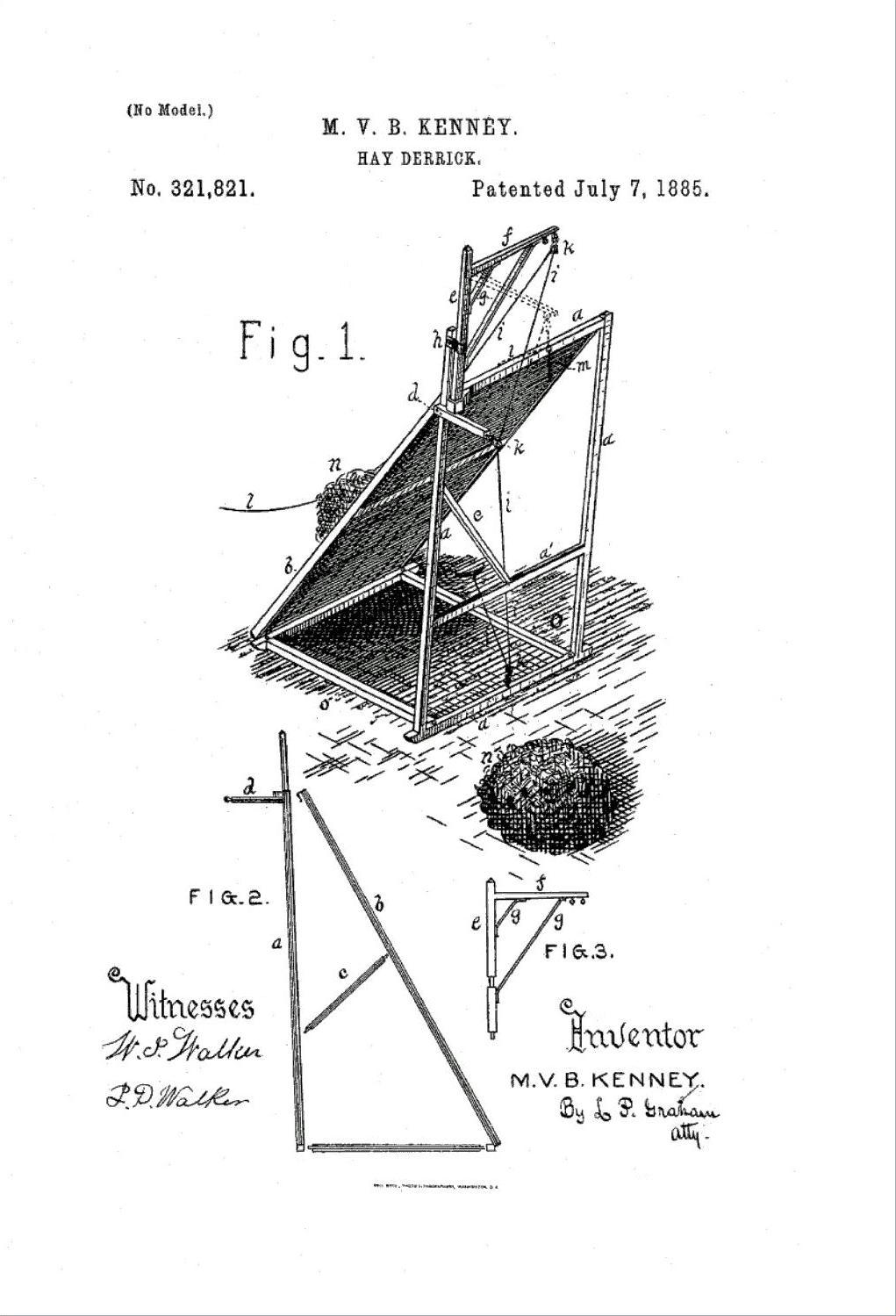
In the drawings accompanying and forming a part of this specification, Figure 1 is a perspective
view of my device, and Figs. 2 and 3 represent detached portions of the same.
a represents a frame approximately vertical in position.
b is an inclined plane supported by vertical frame a.
c is a brace for the central portion of plane b.
d is an arm rigidly attached to one side of frame a.
e is the upright support for swinging arm f.
g represents braces extending from upright e to arm f.
h is an upward extension of frame a, to which crane e f is attached.
i is a rope used for elevating purposes, and k k k are pulleys for the same.
l is a rope used to operate the hay-fork and pull the same back over plane b after the hay
has been delivered.
m indicates the hay-fork in suitable position to discharge the hay.
n represents a load of hay in transit, and n' shows the position of the same after being discharged from the fork.
o o are braces that connect the bottom portions of upright frame a and inclined plane b.
In operation, the hay is drawn up to the foot of incline b in any suitable manner. A fork
attached to an end of rope, i, is used to secure the same, and by means of a horse or other
suitable power attached to the other end of said rope the elevating is effected. When the
hay rises clear of the top of the incline b, the direction of the tension is such as to cause arm
f to swing around into the position indicated by dotted lines in Fig. 1. While hanging in
this position the fork is tripped by means of cord l, and drawn back over plane b in position
to descend for another load.
The entire device is capable of being disconnected for the purpose of transportation
and storage, (see Figs. 2 and 3,) where such disconnection is indicated.
The crane is supported by a suitable block on frame a, and its attachments are such as to
permit ready disconnection.
In addition to stacking hay, my device may be used for loading hay from a stark??? onto a
wagon, may be used for digging wells, swinging up a beef, and for other purposes that derricks
are commonly applied to.
I claim as new and desire to secure by Letters Patent
- The combination, in a hay-derrick, of frame a, inclined plane b, arm d, upright h,
crane e f, pulleys k k k, and elevating-rope i, adapted to have connected thereto a hay-fork,
as and for the purposes set forth.
- The combination, in a hay-derrick, of detachable frame a b o o, crane e f, pulleys k k k,
elevating-rope i, and trip-cord l, adapted to operate the hay-fork and return the same over
the incline b after a discharge has been effected.
In testimony whereof I sign my name in the presence of two subscribing witnesses.
M. V. B. KENNEY.
Attest:
I. D. WALKER,
L. P. GRAHAM.