To all whom it may concern:
Be it known that I, MORGAN WRIGHT, Of Sullivan, in the county of Moultrie and State of Illinois, have invented
certain new and useful Improvements in Bee-Hives ; and I do hereby declare that the following is a full, clear,
and exact description of the invention, which will enable others skilled in the art to which it pertains to make
and use the same, reference being had to the accompanying drawings, and to the letters of reference marked thereon,
which form a part of this specification.
This invention has for its object to provide a hive having superior advantages for protecting the bees from moths
and the extremes of heat and cold.
It consists in the peculiar construction and arrangement of the several parts, as will be hereinafter fully
explained and set forth in the claim.
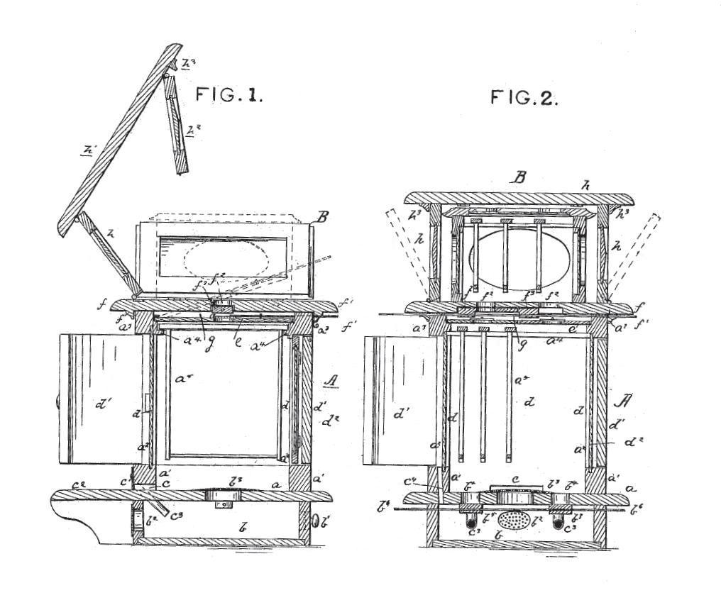
In the drawings, Figures 1 and 2 are vertical cross-sections made on lines drawn through the center at right
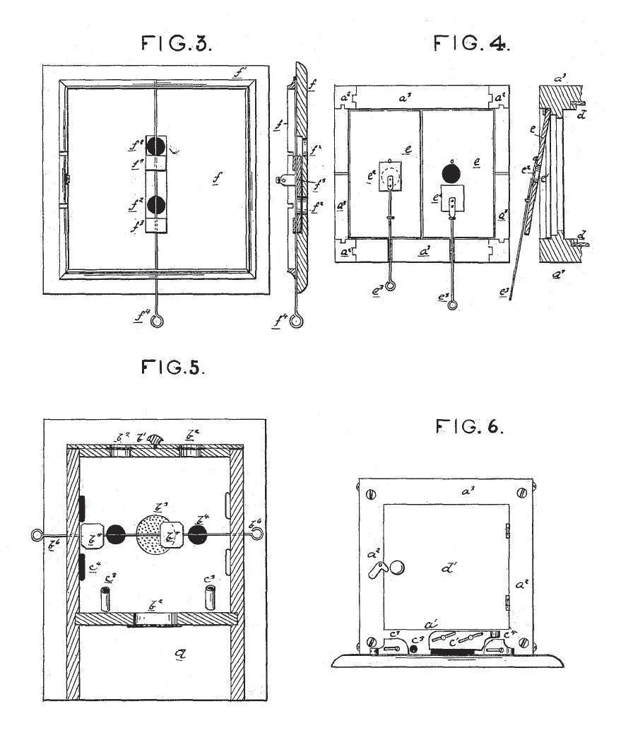
angles to each other. Fig. 3 is an under-side view of the upper casing. Fig. 4 is a plan and section of the top
of the under casing. Fig. 5 is an under-side view of the main floor or base-board of the under casing, showing the under chamber in cross horizontal section. Fig. 6 is a side elevation of the under casing.
The hive is composed of two principal parts, viz., an under casing, A, and an upper casing, B, which maybe
separated when desired. The under casing is composed of the base-board a, to which are affixed the sills a1,
corner parts a2, and plates or top bars a3, all of which are firmly united together, giving a substantial frame,
to which the several parts of the under case are affixed. On the under side of the base-board a I have provided
a sub-chamber, b, for uses hereinafter specified. This sub-chamber b has a door, b1, ventilators b2, and has
leading from it into the chamber of the casing A the ventilator b3, covered by the thin wire-gauze, and the
passages b4 b4, which are covered by slide-valves b5, operated from without by the rods Y. Through one of the
sills a', next the base-board a, I form the openings c, through which the bees enter the hive. The base-board
is extended on this side of the hive to provide an alighting-platform for the bees. The opening c is closed,
when desired, by a slide. c3 el are two small tubes placed in the front of the hive and in either side of the
entrance c, and inclined downward into the sub-chamber b. These tubes are to permit moths to enter the sub-chamber,
where they may be killed.
Opening from the sub-chamber upward through the sills and into the (lead air-chamber, hereinafter described, are
a series of passages, c4, which will permit moths to enter the dead-air chamber, where they may be readily got
at and killed. The outer ends of these moth-tubes may be closed by slides c5.
Within the openings made by the corner-posts a' and plates a3 and sills a', I place the glass panes d. These sit
in toward the inner edges of said framing-bars, and they may all, if desired, be fixed in a separate frame and hinged to the parts 0, so that they can be opened to get at the bees or comb within. Outside of these glass panels I provide doors d1, which are hinged in the same openings, and so that when closed dead-air chambers d2 are provided between them and the panes of glass next them. The plates or top bars a' are provided with suitable ledges a, on which the movable comb-frames & are hung. The upper end of the main chamber of the hive within the casing A is closed by a cap, e, which rests in rabbets cut in the top bars a3 just above the comb-rests O. The caps e are formed, by preference, in two pieces, and each is provided with a bee-passage, el, closed by a slide, 0, operated by rods e3 e3. The caps e maybe readily lifted from their places, as is shown in sectional part of Fig. 4.
f is the base-board of the upper casing, B. It is provided with flanges f1, which fit down outside the top bars, a', of the tinder casing. Through the base f are formed passages f27 through which the bees reach the boxes in the upper casing. The holes f2 are provided with slide-valves f3, moved by a rod, f4.
The cap e and the base f are so arranged with reference to each other that there is provided a (lead-air chamber, g, between them, and ample space in which to operate slide- valves e2 and f3.
To the base f are hinged three of the sides in such manner that they may be turned down to a horizontal position, resting on the outer rim of the said base. The movement of turning down is indicated in Figs. 1 and 2.
The top hl is hinged to one of the sides h, and to the top is hinged the fourth side, V, so that when raised it folds inward, as shown.
The vertical edges of the side h h2 are rabbeted so that when folded and the lid h' closed down on them, they lock firmly together, forming a compact and tight casing. Short flanges h3 are fixed on the lid, which fit outside the upper ends of the sides It.
This construction enables me to open up the hive and have at hand a suitable table or plat-.form on which to place empty or full boxes when removing honey. The work is thus greatly facilitated.
Within the casing B, I place the surplus-honey box or boxes, as shown, which boxes are provided with glass sides, that the progress of the work of the bees may be inspected.
The advantages of this hive will be apparent to any bee-culturist.
I have provided dead-air chambers almost entirely surrounding ing the main hive, while the facilities for driving the bees from one chamber to another are of a superior character.
The bees can be, if desired, driven into sub-chamber b. It is often found necessary to remove bees from their hive for various purposes. In my hive they can be driven and secured in the sub-chamber, and there retained until the necessary work in the main hive A is completed, after which they can be let back, and thus any confusion or injury to the swarm is prevented.
The well-known habits of the moth will take it through the tubes c3, and thence into the dead-air chamber d2 as it seeks to reach the comb in the hive.
The most perfect ventilation is secured, and the dead-air chambers are a preventive against the extremes of heat and cold.
The casing B may be entirely removed from the casing A, if desired, and the latter can be covered by a plain board held down by any suitable means.
What I claim as my invention is
The improved bee-hive composed of the main casing A and upper detachable casing, B, having the sub-chamber b, and provided with suitable ventilators and bee-passages and cut-off valves, and having the glass panes d and the doors d1 arranged within the openings of the framing, so that dead-air chambers d2 are provided, surrounding the sides of the comb-chamber, and having the cap e let down into the top bars, a-, so as to provide the air-chamber g, and having the moth-passages c3 and el leading into the chamber b and chambers d, substantially (sic) as and for the purposes set forth.
In testimony that I claim the foregoing as my own I affix my signature in presence of two witnesses.
MORGAN WRIGHT.
Witnesses :
W. G. PATTERSON, A. P. LACEY.