|
To all whom it may concern:
Be it known that I, FRANCIS M. GREEN, Of Sullivan, in the county of Moultrie, in the State of Illinois, have invented a new and useful Machine for Harvesting and Cutting Up on the Field Cornstalks; and I do hereby declare that the following is a full and exact description thereof, reference being bad to the accompanying drawings, and to the letters of reference marked thereon.
The nature of my invention consists in a new and useful machine for simultaneously felling and cutting up cornstalks, as hereinafter fully described.
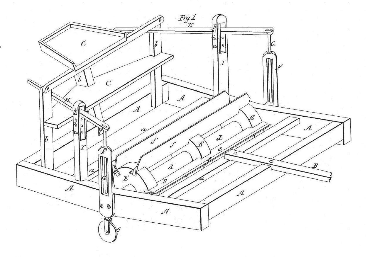
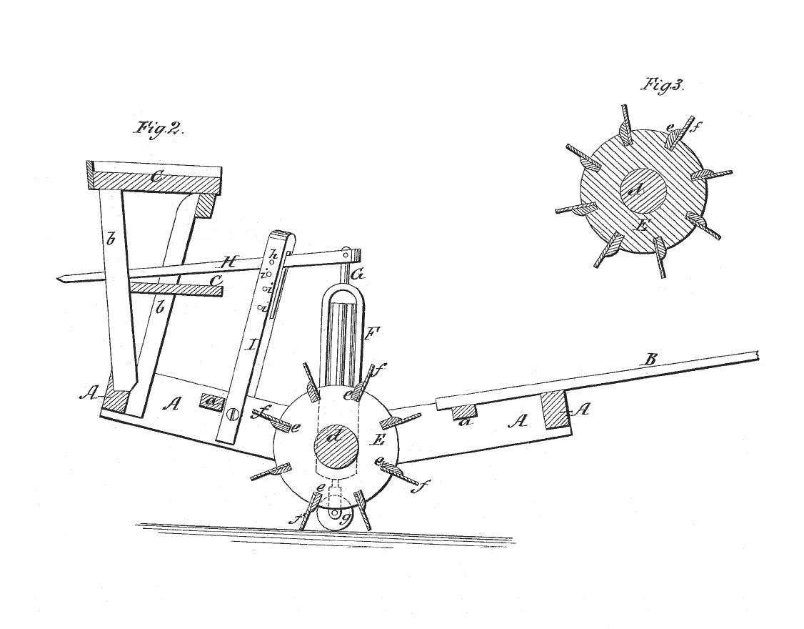
To enable those skilled in the art to make and use my invention, I will proceed to describe its construction and operation, referring by letters to the accompanying drawings, forming part of this specification, where Figure 1 represents a perspective view of my machine; Fig. 2, a vertical longitudinal section through the center of the same, and Fig.3 a cross-section through the center of the knife-cylinder or cutter.
Similar letters denote the same parts in the different views.
A represents the main frame of the machine, the form of which will be perfectly understood from the drawings. Said frame is strengthened by suitable braces or cross-ties, a a, and is furnished with a tongue or pole, B, at the for ward end, while at the rear end is erected a frame-work, b b b, which carries a conveniently-arranged seat, C, and foot-board, c, for a driver, who also is to manage the machine.
D is the cutter or knife cylinder, which is constructed (as seen in the different figures) of a central shaft, d, and three or more circular disks or heads, e e, &c., in the peripheries of which latter is arranged a series of knife or cutter stocks, e e, carrying knives f f, running longitudinally along the peripheries of the heads e e, the stocks e e being accommodated and secured in grooves formed in the faces of the said beads or disks, and secured in position by a wedge or screw, or simply fitted in closely and retained by their friction. The shaft d of the cylinder or cutter has formed in each of its ends a suitable journal, which runs in a bearing formed in the inner surface of each side of the main frame A, near its center, and at the bend or angle of said frame.
f f are two standards, arranged vertically on the outer surfaces of the two sides of the main frame A, and firmly bolted or otherwise secured thereto, about the middles of said sides or at their bends, as seen at Figs. 1 and 2. Said standard f is so constructed (with a vertical longitudinal hole or bearing) as to accommodate a vertical shaft, G, passing up and clown through its whole length, and projecting some distance above and below the said standard. Said shaft is capable, of moving lengthwise up and down in the said standard, and is furnished at its lower end with a suitable wheel, g, while to its upper end is pivoted the forward end of the lever H. Said levers H are pivoted in vertical slotted stands I, projecting upward from the main frame A, a short distance behind the standards F, and their rear ends converge toward each other, passing sufficiently far from and below each side of the seat C as to enable the driver to conveniently reach and press them down, for the purposes to be described. The pins or pivots h h, which form the fulcrums of the levers E, are adjustable up and down in a series of holes, i i, in the stands I.
When the machine is in operation the whole of its weight rests upon the cylinder, consequently upon the cutting-knife, and thus insures the effectual severance of the stalks. When it is desired to convey or run the machine from one place to another without operating the knives, the driver simply presses down the rear ends of the levers H H into the position seen in red at Fig. 2, whereby the vertical shafts g are caused to descend in their bearings in the stands F, or the whole machine to be lifted and its weight thrown onto the wheels g g, on which it may travel, the cutting-cylinder d being raised so as to clear the surface of the ground.
The operation of my machine is very simple, and may be readily understood from the following -- the effect of the knives and other parts on the stalks being illustrated in Fig. 2 of the drawings: The machine, being drawn by adequate animal power of any kind, is brought into contact with the rows of stalks, (the number of rows taken in at one cut depending on the length of cylinder,) which are first slightly bent down before the machine by the forward beam of the frame A, as seen at Fig. 2. The knife-cylinder then follows onto them, its knives f successfully striking down and severing the stalks, or chopping them up into certain lengths. The knives f may be arranged any distance apart on the periphery of the cylinder-heads E. In the machines which I have built they are arranged from four to six inches from each other.
It will be observed that by my machine the stalks are simultaneously harvested or cut down and chopped up into any required length of pieces, while the machine embraces no complication of machinery, but is so simple as to be of little expense and require little repair, while at the same time, with little power and in the most inexperienced hands, it is effectual in accomplishing the desired result.
Having described the construction and operation of my machine, what I claim therein as new, and desire to secure by Letters Patent, is --
The knife-cylinder D, constructed and operating as described in combination with the supporting- wheels g g and the mechanism for operating the same, the whole arranged substantially as described, for the purposes set forth.
In testimony whereof I have hereunto set my hand this 10th day of June, 1858.
FRANCIS M. GREEN.
Witnesses:
JOHN R. EDEN,
JOHN R. MCCLURE.
|